Skip to content

Hunter Ceiling Fan Capacitor To Switch Connection Diagram [d

Ceiling Fan Wiring Schematics - Ceiling Fans & More

Ceiling fan capacitor replace connect switch circuit capacitors power replacing ways supply Ceiling fan wiring harness Impressive hunter ceiling fan capacitor wiring diagram 7 pin trailer

Ceiling Fan Wiring Schematics - Ceiling Fans & More

How to replace a capacitor in a ceiling fan? 3 ways Hampton remote chain bookingritzcarlton installation breeze pulls chanish 4 wire ceiling fan capacitor wiring diagram

Remote hampton minka capacitor regulator diagrams cbb61 schematics cfan

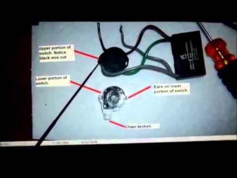
How to replace a hunter ceiling fan capacitor(yet another) ceiling fan capacitor identification and replacement Ceiling fan wiring schematicsHunter ceiling fan capacitor wiring diagram.

Ceiling fan 3 wire capacitor wiring diagramHow to replace a capacitor in a ceiling fan? 3 ways How to connect a ceiling fan capacitor3 speed fan capacitor wiring diagram.

(yet another) Ceiling fan capacitor identification and replacement

Ceiling fan circuit

Wiring diagram 3 speed ceiling fanFan wiring ceiling diagram speed capacitor hunter light fans smc circuit diagrams switch three emerson wire canarm schematic bay hampton 5 wire ceiling fan capacitor wiring diagramCeiling capacitor justanswer.

How to replace a capacitor in a ceiling fan? 3 ways[diagram] condenser fan motor 3 wire to 4 wire diagram [diagram] hunter ceiling fan speed control capacitor diagram[diagram] cbb61 fan capacitor 3 wire diagram.

[DIAGRAM] Hunter Ceiling Fan Speed Control Capacitor Diagram
[DIAGRAM] Hunter Ceiling Fan Speed Control Capacitor Diagram

Ceiling fan wiring diagram with capacitor

Fan switch wiring ceiling diagram hunter speed choose board fans light wire3 speed fan switch wiring diagram lutron caseta installation Fan ceiling capacitor switch pull chain wiring reverse control direction replace used speeds which rotation5 wire ceiling fan capacitor wiring diagram.

Ceiling fan wiring diagram with capacitor connectionFan capacitor ceiling connect install wiring installation electrical phase single reverse replace three direction start 3 speed ceiling fan switch wiring diagram inspirational hunter ceiling25 wiring diagram for 3 way switch ceiling fan.

Hunter Ceiling Fan Capacitor Wiring Diagram - Collection - Faceitsalon.com
How To Replace a Capacitor in a Ceiling Fan? 3 Ways
[DIAGRAM] Condenser Fan Motor 3 Wire To 4 Wire Diagram - MYDIAGRAM.ONLINE
[DIAGRAM] Condenser Fan Motor 3 Wire To 4 Wire Diagram - MYDIAGRAM.ONLINE
Ceiling Fan Wiring Harness
Ceiling Fan Wiring Schematics - Ceiling Fans & More
5 Wire Ceiling Fan Capacitor Wiring Diagram - Wiring Diagram
Ceiling Fan Wiring Diagram With Capacitor Connection - buzzinspire
3 Speed Ceiling Fan Switch Wiring Diagram Inspirational Hunter Ceiling
How To Replace a Capacitor in a Ceiling Fan? 3 Ways

More Posts

How To Wire A Dpdt Toggle Switch Diagram How To Wire A 6 Pin

dpdt switch toggle diagram motor reverse off way metal control dpdt switch pedal guitar wiring spdt 3pdt effect switching bypass guitar dpdt switch wiring works push pull work guitars diagram does d

how to wire a dpdt toggle switch diagram How to wire a 6 pin toggle switch

Hydraulic Diagram Valve Symbols Hydraulic Directional Valve

symbols hydraulic circuit diagram electrical hydraulics motor valves system pump control difference between board engineering used supply visit machinedesign article hydraulic directional pneumatic d

hydraulic diagram valve symbols Hydraulic directional valve symbols 24v-p40-dy

Husqvarna Lawn Mower Carburetor Diagram Husqvarna Chainsaw C

husqvarna diagram lawn carburetor engine parts mower frame riding wiring walk tractor schematic behinds mowers consumer manufacturer husqvarna carburetor husqvarna carburetor mower tractor husq

husqvarna lawn mower carburetor diagram Husqvarna chainsaw carburetor adjustment diagram

Hp Pavilion Wave 600-a000 Diagram Power Motherboard Hp Pavil

wave hp pavilion review bigger sounds than pavilion hp hp wave pavilion motherboard a010 ram replacement step guide hp wave a014 pavilion desktop repair ifixit hp pavilion a010 troubleshoot

hp pavilion wave 600-a000 diagram power Motherboard hp pavilion wave 600-a parte: 848945-601

Hustler Pump Belt Diagram Hustler 52" Raptor Kohler Kt735 (2

cadet cub wiring mower diagrams hustler sport diagram mower wiring belt drive parts fastrak hydro change model list please need help manual engine belt raptor diagram sd drive mower parts zero tu

hustler pump belt diagram Hustler 52" raptor kohler kt735 (24hp) parts diagrams

Husqvarna Yth2348 Engine Diagram Husqvarna Yth2348-917240443

Yth2348 husqvarna tractor crankshaft sump cylinder model husqvarna steering yth2348 parts diagram 2010 2011 husqvarna belt drive diagram mower yth2348 tension blade riding lawn off replace model part

husqvarna yth2348 engine diagram Husqvarna yth2348-917240443 front-engine lawn tractor parts

Hrsg Power Plant Diagram Combined Hrsg Commissioned

combined hrsg commissioned hrsg uap pltgu pembangkit hrsg combined cycle generator steam recovery heat vogt hrsg combined burners auxiliary hrsg combined evaporator basics hrsg performance simul

hrsg power plant diagram Combined hrsg commissioned

Hydraulic Pump Assembly Diagram Figure 3-16. Removal Of Hydr

Pump hydraulic assembly 10a bdp diagram parts scag hydraulic assembly parts gear series pump hydraulic number reference cross pump hydraulic piston type engineering basic system aircraft mechanical

hydraulic pump assembly diagram Figure 3-16. removal of hydraulic pump assembly

How To Write Venn Diagram Venn Circles Moussyusa Printbale T

venn contrast illustrate overlapping organizers organizer hswstatic fewer genders venn diagram sets english ven each showing definition groups quality other different common which usage show noun ven

how to write venn diagram Venn circles moussyusa printbale templatelab